 This is the first in series of 3 complementary caches. This park is a popular spot for the locals to fish away the weekends. There is a play area between the little streams and wetlands that feed into the central dam. Stealth will be required to retrieve the caches.While there is no tree climbing neccessary, but you can if you want to, some stretching of the limbs is recommended. Plan your route carefully to avoid the natural hazards (ducks and streams).
Digital gates are comprised of combinations of transistors to perform specific tasks and give a specific output with one or more digital inputs. Each logic gate type has its own symbol and boolean algebraic equation. Set out below are four types of logic gates, with their associated truth tables. A truth table shows what the output value Y will be for any given set of input values (a shortcut so that you do less maths).
The other four are described in Digital Evolution 2: Zero is Hero.
BUFFER LOGIC GATE
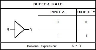
This gate give the same output as its input. This circuit is most often used as an amplifier, increasing the input voltage to a higher voltage value so that it can operate relays or more volume to your speaker.
Boolean algebra is the mathematical way of showing how a gate works. There is only ever one of two answers, that is 0 or 1. A Buffer logic gate's output value always matches its input value, so its written as A = Y. For exmple if input A is 1, than the output Y is also 1.
AND LOGIC GATE
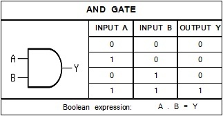
This Logic gate demands that all inputs are true (value 1) to give a true output. This logic gate will be used when your need group of items to be true before it outputs a true value.
The AND gate is expressed as multiplication in a boolean equation. All the input values are multiplied with eachother to determine the output value.
For example if A =1 and B = 0, then it can be written as 1 x 0 = 0, this can be seen in the second line of the truth table.
OR LOGIC GATE
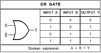
This logic gate demands that any input is true (value 1) to give a true output.
The OR gate is treated as an addition equation in boolean algebra, the big thing to remebmber is the answer can never be more than 1.
For example if A = 1, and B = 1, then using the boolean equation 1 + 1 = 1, as also shown in line three of the truth table.
XOR LOGIC GATE
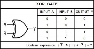
This logic gate often get used as a differentiator. It will give a true output as long as the inputs are different.
A new notion appears in boolean notation here. It is a line above an input value. It is the NOT line. When this found in an equation the opposite value is used in the equation. So if input A is 1, then you insert a 0 into the equation, and if A is 0 then you use 1.
For example A = 1 and B = 0, the equation will look as follows: (0x0)+(1x1)= Y, simplified into 0 + 1 = Y , finally solving Y = 1.
The Bigger Picture
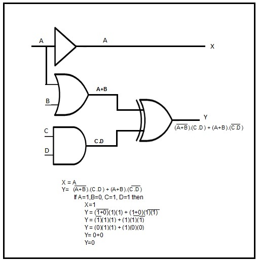
These gates can be used in combinations with eachother in more complex senarios.
For an example below is a circuit with all four types in it. Points A, B, C, and D represent various inputs and X, and Y are the outputs.
If A, C, and D are true inputs (vaue of 1) and B is 0 you will get X and Y output values as worked out below.
And so many leaves make up a tree.
Dont forget to find Digital Evolution 2: Zero is Hero (GC8HG9M), and Digital Evolution 3: Zeroed in One (GC8HGA0)