When I was young, I spent a lot of time sick. To entertain me
and keep my mind engaged, my father taught me things from his job:
Electrical Engineering. Specifically, he taught me binary logic in
the form of logic gates and truth tables.
When I was an Electrical Engineering student, myself, our first
big project was similar to what I created here.
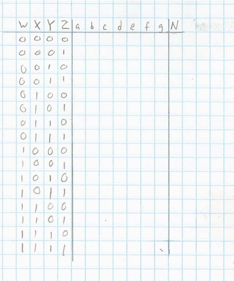
In the image below is a "truth table" with four inputs (W, X, Y,
Z) and seven outputs (a, b, c, d, e, f, g) and a column (N) for you
to fill in the answers.
The second image contains samples of each of the three logic
gates used in this puzzle. It also contains a diagram of the
seven-segment display mapping the outputs of the puzzle to the pins
of the display to make the numbers.
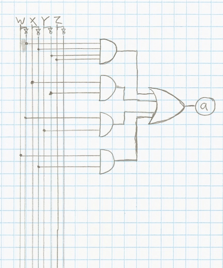
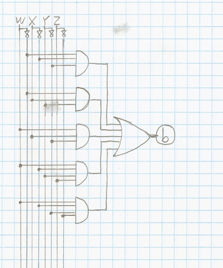
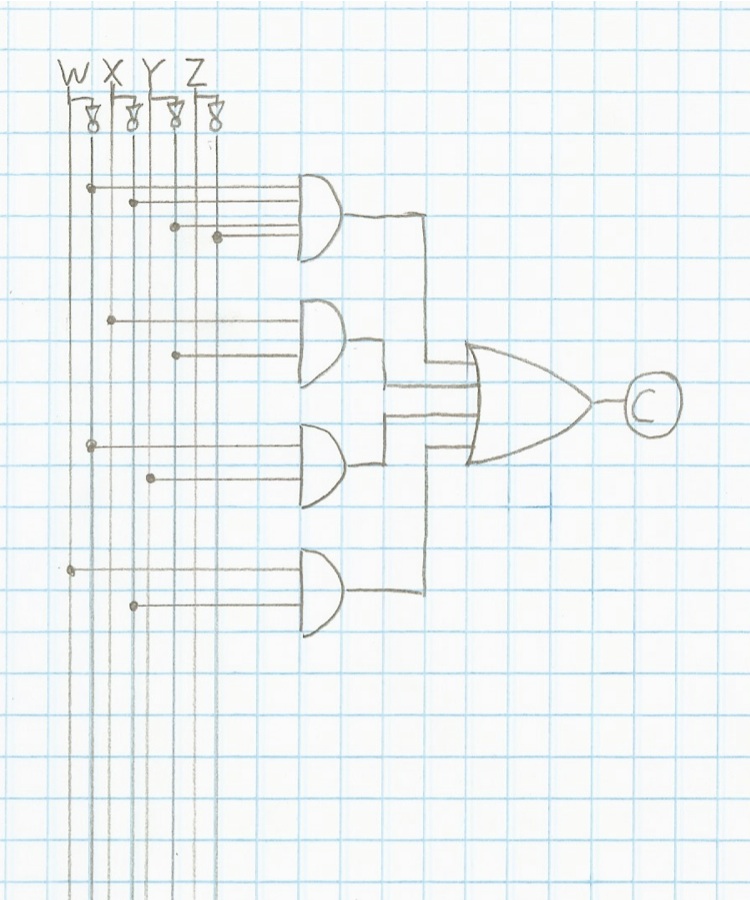
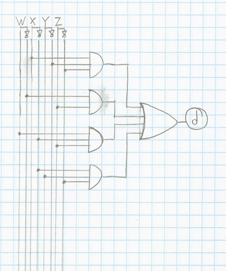
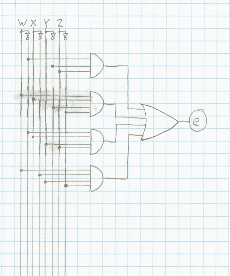
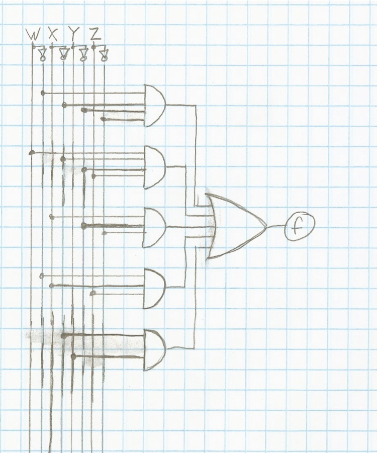
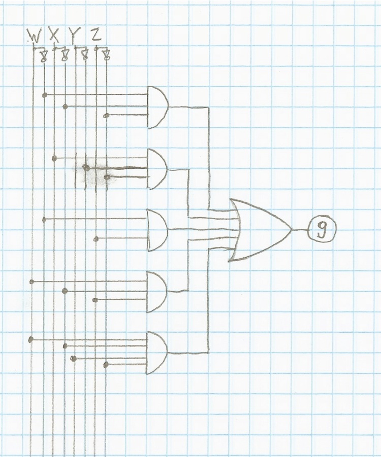
The last seven pages each contain the logic circuit for one of
the outputs. To fill in the table, take a row of inputs and plug
the values into the circuit and write down the output (a one or a
zero) in the corresponding spot in the table.
For each row the outputs tell you which segments in the display
are lit, creating a number for the coordinates.
In most cases, the equations could be further simplified using
additional types of logic gates and configurations, but for
simplicity sake I have kept all the first column of gates as "AND"
gates which filter into the final "OR" gate for each output.
Additionally, for each input I have also created a inverse ("NOT")
version of the input.

You can download the full set as a
PDF worksheet if you like.
It should be very clear if you are correct or not, but you can
check your answer for this puzzle on
Geochecker.com.