
This is the second in series of 3 complementary caches. This park is a popular spot for the locals to fish away the weekends. There is a play area between the little streams and wetlands that feed into the central dam. Stealth will be required to retrieve the caches.While there is no tree climbing neccessary, but you can if you want to, some stretching of the limbs is recommended. Plan your route carefully to avoid the natural hazards (ducks and streams).
Digital gates are comprised of combinations of transistors to perform specific tasks and give a specific output with one or more digital inputs. Each logic gate type has its own symbol and boolean algebraic equation. Set out below are four types of logic gates, with their associated truth tables. A truth table shows what the output value Y will be for any given set of input values (a shortcut so that you do less maths). All the logic gates listed below are inverse to the gates listed and described in Digital Evolution 1: One is Fun. They are differentiated by means of a circle at the output side of the symbols. In order to invert the calculated output value, output value 1 becomes 0 and output value 0 becomes 1.
NOT GATE
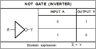
This logic gate is also known as the inverter. Its output is always opposite to the input. It works opposite to the buffer gate. The NOT logic gate symbol is the same as the BUFFER logic gate symbol but with an added circle on the output side. This tells us the invert or switch the output value that we would have worked out with the BUFFER gate.
The Boolean equation tells us to use the opposite input value by placing a line above the input value. for example if the input A is 0 then the equation will read 1 = Y.
NAND GATE
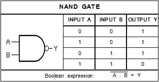
The NAND Logic gate is the inverse of the AND logic gate. For this logic gate to have a true output value(1) it must have at least one false input value (0). Another way of stating it would be that no further action is required (output = 0) if all the conditions (inputs = 1) are met.
The boolean equation is similar to that of the AND logic gate except that the input expression is inverted. If the bar is unbroken over a portion of the equation, it must be solved before getting inverted. For example if input A =1 and input B =0, then the equation is  ,which is simplified to
  , finally solved as Y = 1 after inverting the 0.
NOR GATE

The NOR gate is the inverse gate of the OR logic gate. If all inputs are false (value 0) then the out value will be true (value 1).In any other instance where any input value is true the output vlue will be false.
Again in the Boolean equation the final value calculated on the left needs to be inverted to get the Y value. For example if input A is 0 and input B is 0 then A+B is 0+0 = 0, invert this to get 1, therefore Y=1.
XNOR GATE

The XNOR logic gate is the inverse of the XOR logic gate. This logic gate is also known as a comparator. If the inputs are the same, then the output is true (value 1).
In the boolean equation the individual inputs need to be inverted before calculating the answer. This is shown by the inputs having individual NOT lines indicated by the letters. For example if input A is 1 and input B is 0 then the modified equation will look as follows: ( 1 x 0 ) + ( 0 x 1 ) = Y, simplified to 0+0 = Y, therefore Y=0.
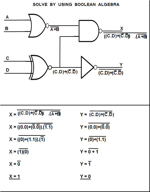
THE BIGGER PICTURE
These gates can be used in combinations with eachother in more complex senarios.
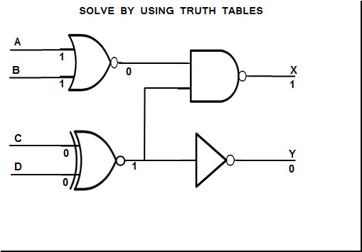
For an example below is a circuit with all four types in it. Points A, B, C, and D represent various inputs and X, and Y are the outputs.
Consider if A and B are true inputs (vaue of 1), and C and D are false inputs (value of 0).Based on the diagram below you will get X and Y output values as shown. This diagram can be solved by either using the relevant truth table for each logic gate or by calculation using boolean algebra.
Ones and Zeros seem to be polar opposites
Dont forget to find Digital Evolution 1: One is Fun (GC8HG98), and Digital Evolution 3: Zeroed in One (GC8HGA0)